
But does it go to 11?
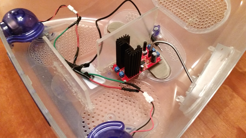
The amp in its natural habitat
So, my fish tank needed an amp.
What?
The sound levels in the iMac speakers are too low when driven by the Raspberry Pi that powers the thing, and since I want it to be an internet jukebox for my office, that’s not going to work very well. After much searching for the right amp to drive the speakers, I decided to build one instead. Why? That’s not really a question one asks around here.
It’s been a long time since I did any significant electronics work, and my skills probably weren’t up to designing one from scratch in the first place. Fortunately, Sparkfun makes a kit, the STA540 Audio Amplifier. Two channels, 38W, and according to theory (and a calculator I found on the Internet) more than enough to meet my needs without overdriving the speakers. Plus, it fits in the available space under the fish tank.
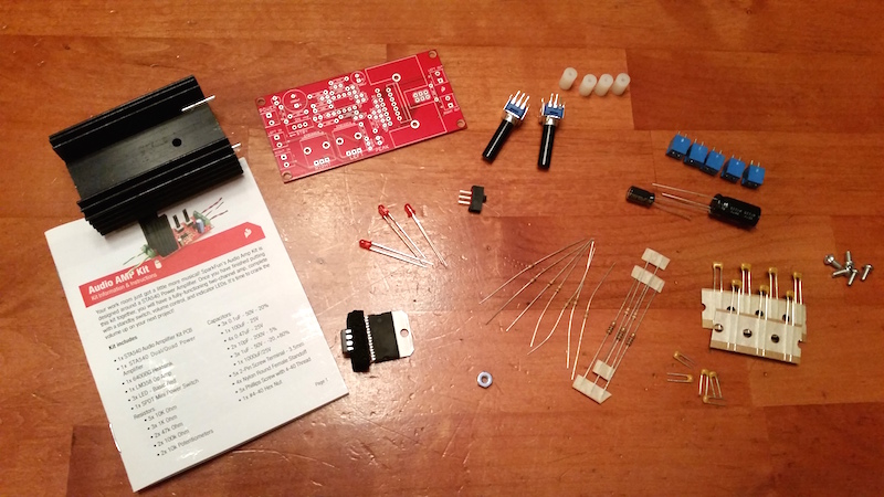
The kit, on our dining room table (don’t tell Angela)
I was pretty pleased with the kit itself. Reasonably packaged – aside, maybe, from the 7 loose resistors, 5 of which are coded Black-Brown-Orange and two Black-Brown-Yellow – and nicely designed. Plenty of room for all the components on the PCB without crowding, and excellent instructions. A confident novice with a little soldering experience should have no trouble building the kit. That’s a good thing, because it’s been long enough “novice with a little soldering experience” is probably a reasonable assessment of my current skill level.
The kit walks through the process in a reasonable fashion, smaller components first. Despite the years of rust I quickly remembered the little tricks and details – soldering iron goes in your non-dominant hand, use the dominant hand for the solder. Various ways to clamp components in place with the little third-hand stand. How to burn the crap out of your hand with a soldering iron. (Skip that last one.)
I expected the kit to take a couple of evenings to assemble, but once I got into a rhythm it went together very quickly. I didn’t get started until after 8, and I finished by 10:30. Then of course it took another 40 minutes to find and eliminate all the bad solder joints and other issues, but even so it’s still one evening’s project.
I did make a couple of minor adjustments –
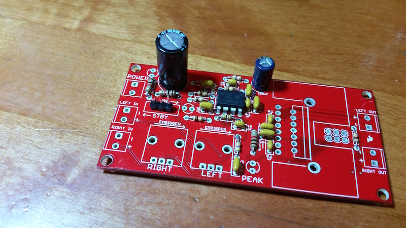
Mid-assembly with headers in place of the standard switch
There on the left, in front of the large capacitor, is a box labeled “STBY”. That’s intended to be the standby/on switch for the amp (it’s partially powered whenever it’s connected to power, so it’s not really “off”.) But I want to mount this inside the base of the fish tank, and it won’t be easily accessible. So instead I soldered in a three-pin header and wired the switch using jumpers so I can put the switch in the old IO port panel. I originally intended to wire the LEDS and potentiometers the same way, but I changed my mind. First, the LEDs will be visible in the amp’s mounting location, so running leads to them seemed like overkill. Second, the potentiometers (“volume knobs”) would be a pain to wire that way, and more than likely never adjusted after the first round of testing. So although it goes against my nature, I followed the directions for the rest of the kit.

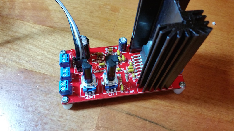
The finished amp with wired switch
Want to know what the slowest process in the world is? Soldering a heat sink.
The kit instructions give a set of instructions for testing the board, which in my case revealed a minor short where solder bridged a couple connections. Once fixed, I showed rare maturity in deciding not to wire it up to a sound source and the speakers and seeing what I get from it. We’ll try that tonight – there’s nothing good on TV anyway. 😉