
MendelMax 3 Build – Day 1
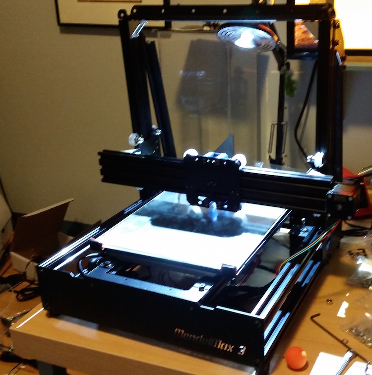
I recently gave in to the temptation to purchase a 3D printer kit, and settled on the Maker’s Tool Works MendelMax 3 as the best combination of final build quality, upgrade capacity, and potential for fun building it. Not included in that list? High quality build documentation.
Which, I suppose, could be considered part of the fun. Yeah, I’m weird.
So, mostly to help myself out with understanding what it is I’m doing, I’m documenting my build as I go; based on the official build guide but including my own notes and observations. This is a single-extruder, full-kit MendelMax 3. I will not attempt to include the steps specific to the upgrade process, because I have no means of doing so.
By the way, if you’re stumbling across this looking for build help – you might want to see if I’ve finished this series of posts first. 🙂
The official build guides do have useful information in them, and can be found here:
Official MendelMax 3 Build Guide
(Edited to add: New, much better, Official Build Guide)
Official V Slot Wheel Assembly & Adjustments
Official MendelMax 3 Bill of Materials (Note: as of February 19, 2015 the BoM was slightly inaccurate)
First, lay out the parts and pieces and check them against the BoM and this plate layout. The goal is to not only confirm that everything you expected is included, but also to familiarize yourself with the parts. There are a lot of them, and having at least a basic familiarity will make the overall process much easier. Give yourself plenty of space, good lighting, and a spot that doesn’t need to be cleared off between build steps. The dining room table your family needs every night is not a good choice. (Ask me how I know!)
Next, there’s a 3D model PDF of the printer. There are a couple of ways it can be helpful, first of course for getting an overview from many different angles, but the best one for me was to open the Tree View, unselect everything, and then select specific components and pieces as I went. It meant I was “building” the printer in the 3D model as I assembled the real printer. It isn’t perfect – there are various small but critical components that aren’t visible, for example – but it’s still helpful.
As you laid out the parts and pieces, you probably noticed the markings on the bags of hardware. Specifically, all the bags are labeled with the hardware sizes, such as M5-16. However, two bags are unmarked, the largest collections.
The largest has 75 M5-8 screws, and you’ll use them constantly throughout the build process. The second largest set contains 25 M5-10 screws. Don’t confuse them.
Also, your kit will potentially include three kinds of T-nuts – a short rectangular type with a line across the top (T-Slot nut), a longer rectangular type (most common, the “regular” T-nut), and a third kind with a roller ball cast into it. You will use the T-nut type for any general construction step; the third kind, a Post-Install T-nut, is installable after the ends of the extrusion are no longer accessible which is very handy. Save them for that situation or when specifically called for below.
In all cases, the protrusion on the T-nut goes towards the center of the extrusion when installed in a channel, not out towards the screw.
If you need help during the build – and it’s very, very likely that you will if this is your first printer – Maker’s Tool Works has an IRC channel (#makerstoolworks) on Freenode, with a web interface here.
Finally, lay out the provided tools, and add some screwdrivers, a square (I used a 6″ speed square), a small file, a good metric ruler or calipers, pliers, scissors, etc. Onward!
Step One: Base Assembly
You will need:
- Front and Rear panels (U and T)
- 4 of the 6 240mm extrusions
- 8 M5-8 machine screws
- 8 M5 washers
- 4 T-nuts
- Square
The Base Assembly is really nothing more than a big empty box. The two plates are the front and rear panels of the printer, and the four extrusions make framework sides the rest of the printer builds on.

Your printer after Step One. (Actual printer might not glow.) Image (c) Maker’s Tool Works
Each extrusion has a tapped hole in the center of each end. Start by lining up one of the extrusions between the holes in the bottom left corner of each plate. (Note: there are two holes in the rear panel. The larger hole is for power, the smaller for USB. If you prefer to have them reversed, you can flip the panel end-for-end.)
Use two finger-tight M5-8 screws to attach the panels to the extrusion, using two washers on the front screw between the screw head and the panel. Don’t install any washers on the rear screw.
Next do the same for the bottom right. Use your square to keep the frame lined up properly (perfection is not required at this stage, but more attention paid to it now will save time and effort later.)
Before installing the top extrusions, install two T-nuts each in what will be the bottom channel. (Optional: skip ahead to Step Three below and install the Z Motor Mounts now, using these T-nuts.)
For the install itself, copy the bottom extrusions with two washers in the front and none in the rear. Once again, use your square to check that everything is lined up and square.
Step Two: Lower Side Plates
You will need:
- Base Assembly
- Both Lower Side Plates (L)
- 12 M5-8 machine screws
- 24 M5 washers
- 12 T-nuts
- Allen wrench
From the rear of the Base Assembly, you can insert T-nuts into the Inside, Top, and Outside channels of the top extrusions, and the Inside, Outside, and Bottom channels of the bottom extrusions. Insert three each into the outside channels of all four.
Using M5-8 screws and two washers each, attach the Lower Side Plates to the Base Assembly. They should end up flush with the rear, with the flanges up and the single-hole flange at the back.
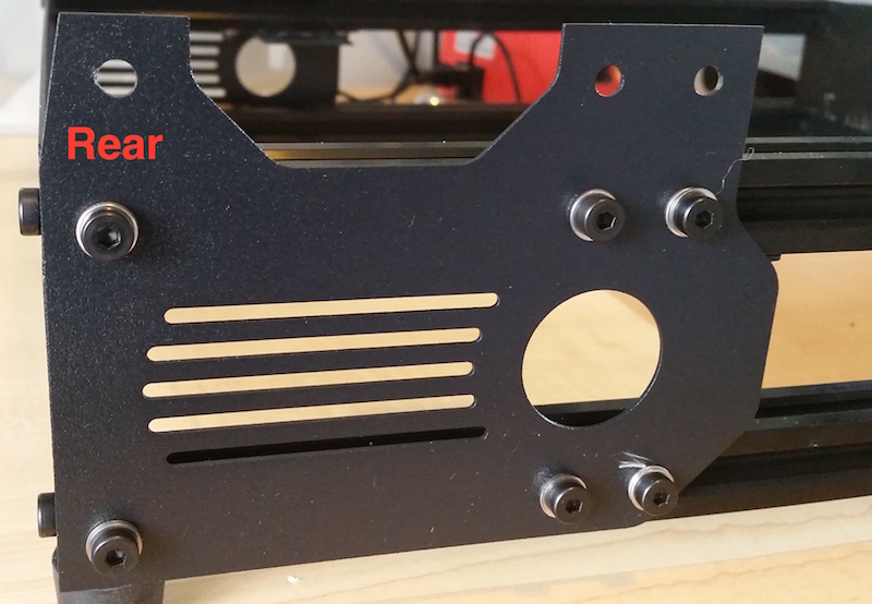
Installed Lower Side Plate.
Ignore the random bits of fluff. It appears the clean room standards of my office are not up to snuff.
Place the Base Assembly on a solid, flat surface and tighten down the screws attaching the Lower Side Plates, then use your square to verify the alignment of the Base Assembly as you tighten down the screws on the Front and Rear panels as well.
Step Three: Z Motor Mounts
You will need:
- Base Assembly
- Both Z Motor Mounts (F) (Note: The Z Motor Mounts changed and now more closely resemble the part labeled E)
- 4 M5-8 machine screws
- 8 M5 washers
- Calipers or accurate ruler
- Allen wrench
The Z Motor Mounts go inside the Base Assembly, attached to the T-nuts you installed in the top frame extrusions in Step One.
There are two ways to position the Z Motor Mounts. The first option is to temporarily install the 2040 (double-width) extrusions, attached to the double hole flange of the Lower Side Plates. Then align the Z Motor Mount’s center to the center of the extrusion using a square. If you use this method, remove the 2040 extrusions when you’re done.
The second option is to use calipers to set the rear edge of the Z Motor Mount 88.5mm from the rear of the extrusion.
Step Four: Base Assembly Feet
You will need:
- Base Assembly
- 4 rubber feet
- 4 M5-14 machine screws
- 12 T-nuts
- Allen wrench
Assemble the feet by inserting a M5-14 screw into each rubber foot from the narrow end. The head of the screw should end up deep inside the rubber foot. Add a T-nut to the end of the screw with the protrusion facing away from the rubber foot.
Turn the Base Assembly over and place it on a flat surface. Slide the T-nuts from one of the feet into each bottom channel on the bottom extrusions and bring the foot all the way to the front of the Base Assembly. Tighten the screw with an allen wrench until the foot is firmly secure on the extrusion.
Add four more T-nuts to each bottom extrusion before adding the final feet at the rear of the Base Assembly, securing them as you did the front feet.
Step Five: Deck Center Plate (Y Axis Assembly)
You will need:
- 2 2020-420mm extrusions
- 2 long V-rails (A)
- Deck Center Plate (B)
- Y-Axis Stiffeners (G)
- 16 M5-14 machine screws
- 8 M5-8 machine screws
- 48 M5 washers
- 25 T-nuts
Slide 8 T-nuts into the top of each of the two 2020-420mm extrusions.
Place one long V-rail on top of each extrusion, with the flange of the V-rail lined up on the outside edge and pointed up. (See MTW photo below)

Detail of V-rail alignment (c) Maker’s Tool Works
Use the holes in the long edge of the Deck Center Plate to space the T-nuts in the extrusion. The precise positioning of the V-rail along the length of the extrusion isn’t important, their purpose is to position the extrusions correctly relative to the width of the Deck Center Plate.
Once you have the V-rails and T-nuts aligned, place the Deck Center Plate on top of the V-rails flush with the flanges on each side. The front and back edges of the Deck Center Plate should overlap the ends of the extrusions by a small amount – position the Plate so it overhangs both by the same amount. Finally, looking at the Deck Plate from the eventual front, the square opening in the plate should be at the front and the long slot should be on the left side.
Finger-tighten 8 M5-10 screws unto the T-nuts, with two washers between the screw head and the plate. Do not over tighten these screws – you’ll secure them in a future step.
Turn the assembly over and slide 5 T-nuts into the bottom channel of the extrusion next to the long slot in the Deck Center Plate (the left extrusion.) Slide four T-nuts into the bottom channel on the opposite, right, side extrusion.
*Loosely* secure the two Y-axis stiffeners to the ends of the extrusions using all but one of the T-nuts you just installed. Use the 8 M5-8 screws for this step, again with two washers between the screw head and the plate.
This picture shows the completed assembly, still upside-down (without the fifth, loose, T-nut in the right extrusion):

Completed Y-Axis Center Deck Plate Assembly (c) Maker’s Tool Works
Step Six: Y-Axis Positioning and Adjustment (Y-Axis Assembly)
You will need:
- Base Assembly
- Y-Axis Center Deck Assembly
- 6 M5-8 machine screws
- 12 M5 washers
- 2 M5 hex nuts
- Square
The overhangs of the Y-Axis Center Deck Plate should allow the Y-Axis Center Deck Assembly to rest on the front and back panels of the Base Assembly, positioned with the stiffeners down and the extrusions just touching the front and back panels at the center set of holes in each panel.
Finger-tighten the 6 M5-8 screws to secure the Y-Axis Center Deck Assembly, two through the front plate into the ends of the extrusion, two through the back plate into the other ends of the extrusion, and final two into the ends of the rear stiffener plate using the 2 M5 nuts. As usual, place two washers between the plates and the screw heads for the center screws – use one on each side of the plates for the fasteners in the stiffener plate.
Using your square, adjust the positioning of the Y-Axis Center Deck Assembly and Base Assembly to ensure everything is square and level. Once you’ve gotten it as square as possible, tighten the four screws in the top corners of the Center Deck Plate and the two attaching the rear stiffener to the rear plate. Adjust the position of the front stiffener to leave a gap of about the thickness of two stacked washers between the front stiffener and the front plate.
Confirm that your combined assembly is still square.
Tighten the eight bottom stiffener screws, then the rest of the Center Deck Plate screws on the right side. Then tighten the rest of the Center Deck Plate screws. This confirms the positioning of your assemblies to keep the printer square.
Remove the Y-Axis Center Deck Assembly by removing the six screws from the rear and front panels.
Step Seven: Y-Axis Motor and Idler Bearings (Y-Axis Assembly)
You will need:
- Y-Axis Center Deck Assembly
- Y-Axis Motor Mount Plate (D)
- Idler Plate (C)
- 2 M3-6 button head screws
- 2 M3 washers
- 1 Stepper Motor (Note: in my kit all motors are identical; some older kits have longer and shorter leads. Use the short leads here.)
- 1 Toothed stepper belt bearing and set screw
- 6 605 bearings
- 1 M5-16 machine screw
- 1 M5 hex nut
- 2 M5-20 machine screws
- 1 M5-8 machine screw
- 12 M5 washers
- 2 Post-Install T-nuts
- 1 T-nut
In order, slide a Post-Install T-nut, the regular T-nut, and the second Post-Install T-nut into the inside channel of the left extrusion. Two slide to the front, one to the rear.
Use the M3 screws and washers to mount the stepper motor to the Y-Axis Motor Mount Plate. I found it best to place the motor with the fixed-position screw first, then add the second in the end of the arc slot farthest from the other mounting holes to make it easier to install the idler bearings.
Next, build the belt router idler bearing. It’s easier to build upside down – place an M5-16 machine screw on its cap, then slide a 605 bearing, an M5 washer, another 605 bearing, and two more M5 washers. Insert them into the hole closest to the motor, with the screw head on the same side as the motor shaft, and use another washer and the M5 hex nut to finish off the bearing. Make sure this one’s tight.
Install the Toothed stepper belt bearing on the stepper motor shaft; the end of the bearing with the set screw hole goes farthest from the motor casing. Position the bearing far enough out on the shaft that the toothed part of the wheel is centered on your idle bearing, and set the set screw against the flat surface of the motor shaft. Tighten it enough to keep it snug, but not so tight you couldn’t remove it again.
Now, the other two holes of the motor mount get another idler bearing (end hole) and a M5-8 screw with two washers. Build the idler bearing exactly as you did the last one, but using an M5-20 screw. It goes into the post-install T-nut, while the M5-8 goes into the standard T-nut. Position the Y-Axis Motor Mount Plate so that the end of the plate is 10mm from the front end of the left extrusion. Really tighten down on the idler bearing screws; they’ll be under near-constant vibration while the printer’s operating.
Finally, build another idler bearing stack exactly like the last one on an M5-20 screw. On top of the double washer, add the small, D-shaped Idler Plate (use the larger of the holes in the plate.) Mount this idler bearing in the second Post-Install T-Nut, and position it at the aft end of the extrusion with the flat side parallel to the end of the extrusion and perhaps 1 or 2mm from the end.
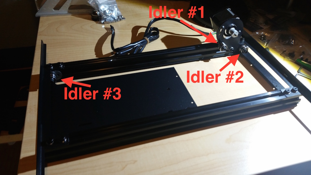
The 3 Y-Axis Idler Bearings, installed
And this is the point where I ended my first day’s build. Tune in next time for more thrilling adventures of discovering you’ve forgotten a T-nut right after closing the end of the extrusion…
3 thoughts on “MendelMax 3 Build – Day 1”
Comments are closed.