
MendelMax 3 Build – Day 2
I recently gave in to the temptation to purchase a 3D printer kit, and settled on the Maker’s Tool Works MendelMax 3 as the best combination of final build quality, upgrade capacity, and potential for fun building it. Not included in that list? High quality build documentation.
Which, I suppose, could be considered part of the fun. Yeah, I’m weird.
So, mostly to help myself out with understanding what it is I’m doing, I’m documenting my build as I go; based on the official build guide but including my own notes and observations. This is a single-extruder, full-kit MendelMax 3. I will not attempt to include the steps specific to the upgrade process, because I have no means of doing so.
By the way, if you’re stumbling across this looking for build help – you might want to see if I’ve finished this series of posts first. 🙂
Day 1 can be found here.
The official build guides do have useful information in them, and can be found here:
Official MendelMax 3 Build Guide
(Edited to add: New, much better, Official Build Guide)
Official V Slot Wheel Assembly & Adjustments
Official MendelMax 3 Bill of Materials (Note: as of February 19, 2015 the BoM was slightly inaccurate)
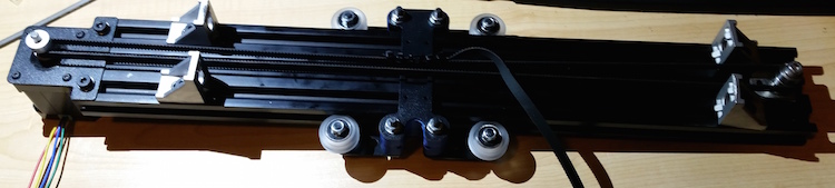
Step Eight: Y-Axis Wheels (Bed Assembly)
You will need:
- Y Bed Plate (N)
- Y-Axis Center Deck Assembly
- 4 V-wheel kits (individual bags shipped with your kit)
- 2 Eccentric Spacer Washers
- 4 M5 washers
Place the Y Bed Plate on your work surface, with the trapezoidal hole at the front. The bends at the sides should be up, and the bends on the front and back, down.
Here’s a YouTube video from the manufacturer of the wheel kit – not that their Eccentric Spacer Washer isn’t the same as the one you’ll use.
The wheels, once assembled, go into the holes indicated in this image:
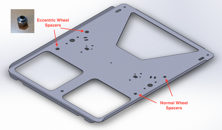
Y Bed Plate wheel layout based on image from Maker’s Tool Works
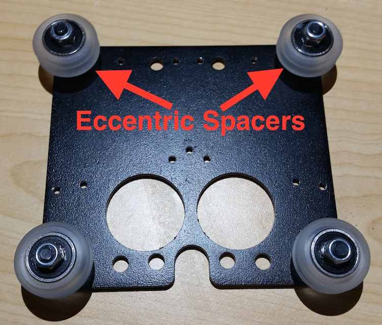
The two wheels on the left side get the normal spacer included in the wheel kit bags, the wheels on the right – with the larger holes – get the Eccentric Spacer Washers, packaged separately. They look like metal hex nuts with a round peg on top and an off-center hole through the peg.
In either case, use the screw from the wheel kit. The wheel ends up on the bottom of the plate. First, slip an M5 washer on the screw and insert it through the plate with the head on the top side of the Y Axis Bed Plate. Place a spacer (Eccentric or Normal as indicated above) over the screw – in the case of the Eccentric spacers, the round peg goes through the hole in the plate. The wheel goes next, then the nut – don’t include a washer between the nut and the wheel.
With all four wheels installed, it’s time to mount the Y Bed Plate on the Y Center Deck Assembly. The flanges on the edges of the Deck Assembly slide into the V wheels; the Y Axis Motor is on the front of the deck assembly. You’ll likely need to turn the Eccentric Spacer Washers to make sure the bed rides smoothly, but when you’re done, it should slide smoothly and easily back and forth.
Step Nine: Y-Axis Belt Installation
You will need:
- Y-Axis Center Deck Assembly
- Y belt offset
- Y belt clamp
- 1 belt
- 4 M3-6 button-head screws
- 2 M3 hex huts
With the bed plate in position on the Center Deck Assembly, look for a rectangular hole surrounded by four small holes on the bed plate in line with the long slot in the Center Deck Plate. Using two of the button-head screws and the two hex nuts, install the Y belt offset here, centered on the rectangular hole. The nuts should go on top of the Y belt offset piece.
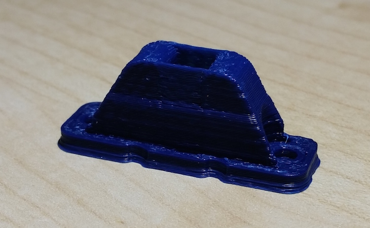
The printed Y Belt Offset part
Once the part is installed, run the bed back and forth to make sure the belt offset rides cleanly inside the slot. It should have plenty of clearance. Then flip the assembly over. Feed the center of the belt through the rectangular hole and offset part, keeping both ends on the top of the bed plate. Install the belt clamp (a small, flat, rounded-rectangle piece of metal with two holes in it) using the other two button-headed screws; it fits with the two small tapped holes in front of the rectangular hole the belt goes through. Capture both ends of the belt.
Flip the assembly over again, and feed the belt like this:
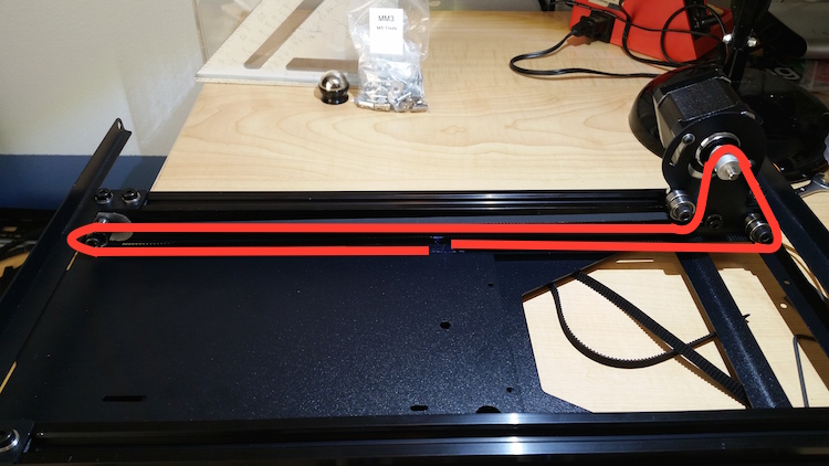
Y Belt Layout
Then loosen the cable clamp, pull the belt tight, and tighten the clamp back down.
DO NOT TRIM THE BELT.
Step Ten: Glass Bed Installation
You will need:
- Y-Axis Assembly
- Glass Bed
- Bed Heater
- Heat spreader (aluminum sheet)
- 3 Glass Clips
- Silicone rubber material
- Black rubber grommet
- Wire loom
- 1 M5-14 machine screw
- 2 M5-20 machine screws
- 2 M5-8 machine screws
- 2 M5 hex nuts
- Scissors
First, take your silicone rubber material and cut it into three pieces. Peel off the adhesive backing and stick each piece to a glass clip. Cover the inside of the short angled piece, and don’t interfere with the slot cut into the long piece.
The first clip attaches in the center of the rear edge of the bed plate. Thread the M5-14 screw from underneath the bed plate through the hole in the glass clip. Nothing goes into the slot on this clip.
The other clips connect at each corner of the front edge. There is a hole close to the edge, and a slot a short distance back. Thread an M5 hex nut onto a M5-20 screw, then thread the screw up through the hole from the bottom side. The slot in the glass clip fits over the screw. Then a M5-8 screw fits through the slot in the bed plate from below and threads into the hole on the glass clip.
When you install the glass bed, it will rest on the tops of the M5-20 and M5-14 screws. Tightening the screws presses the glass into the silicone rubber on the glass clips and holds it securely fixed into position. The rear clip doesn’t move, but the front ones can slide back for installation and removal of the glass bed; you’ll lock them in place with the M5-8s.
Remove the glass from its styrofoam carrier and remove any tape residue on the glass. Heat, rubbing alcohol, and glass cleaner all seem to work reasonably well. If you have protective tape on your aluminum heat spreader, remove it as well.
Position the heater centered in your heat spreader and tape it onto the aluminum sheet at two corners. Bend back the heater at the opposite side and peel back a few inches of backing paper, then carefully smooth the heater down onto the sheet. Working a few inches at a time, peel back the backing and smooth down the heater until it’s fully secured to the aluminum sheet.
Install the black rubber grommet into the large round hole on the opposite side of the bed plate from the Y belt offset. (It’s centered between the wheels.)
Cut about 24cm of wire loom – I used superglue to keep the ends from fraying. Feed the wires from the heater through the loom, then pass the end through the rubber grommet. Secure it to the bed plate with a zip tie through the holes to either side of the grommet.
Place the aluminum sheet (heater down) on the bed plate, and the glass on top of the aluminum sheet.
You can, if you choose, reinstall the Y Axis Assembly in the Base Frame Assembly using the six screws as before. It may be easier to wait until after the electronics are installed.
Step Eleven: Angle Brackets and Idler Bearing (X-Axis Assembly)
You will need:
- The 2060-450mm Extrusion (the three-slot-wide one)
- 4 Right-Angle brackets
- 5 T-Slot Nuts
- 3 605 bearings
- Idler Plate (C)
- 4 M5-8 machine screws
- 1 M5-25 machine screw
- 7 M5 washers
Lay the extrusion flat on your workspace with the channels running across the table in front of you. The channels, from farthest from you to closest, are 1, 2, and 3. Insert two T-Slot Nuts into each of slots 1 and 3, one near each end. Secure a Right-Angle bracket to each nut using a M5-8 machine screw and a single washer. Face the angle braces out from the center, and position them with their outside edges about 30mm from the ends of the extrusion.
One end of the extrusion has tapped M5 screw holes in it; slide a T-Slot Nut into channel 2 and place it about 20 mm from that end. From now on I will refer to this as the left end.
On the M5-25 screw, assemble from the screw head down a bearing, washer, bearing, washer, bearing, washer, Idler Plate, and thread the screw into the T-Slot Nut in the middle channel. Don’t tighten it down yet, no more than finger-tight. If the screw bottoms out – it did on mine – add additional washers as spacers.
Step Twelve: X Motor Bracket (X-Axis Assembly)
You will need:
- The X-Axis Assembly
- The X Motor Plate (E)
- 4 M3-6 button head screws
- 1 Toothed stepper belt bearing and set screw
- 2 T-nuts
- 2 M5-8 machine screws
- 4 M5 washers
Mount the toothed belt bearing on the stepper motor in the same fashion as the Y-axis stepper motor.
Place the motor on your workspace with the gear up, and the wire leads facing towards you. Using the M3-6 button head screws, fasten the motor to the X Motor Plate with the two-hole flange on your right.
Insert two T-nuts in slots 1 and 3 of the right end of the X-Axis Assembly. Mount the X Motor Plate to these T-nuts using the M5-8 screws and two washers each; the motor should be flush with the end of the extrusion, and the geared bearing should be on the same side of the extrusion as the Right Angle Brackets from the last step.
Step Thirteen: X-Axis Carriage (X-Axis Assembly)
You will need:
- The X-Axis Assembly
- The X-Axis Carriage Plate (K)
- 4 V-wheel kits (individual bags shipped with your kit)
- 2 Eccentric Spacer Washers
Assemble the four wheel kits exactly as before, and install them in the corners of the X-Axis Carriage Plate. Note the orientation below:
X-Carriage Wheel Placement
Slide the carriage onto the extrusion, with the plate on the side opposite the Right Angle Brackets. The U-shaped cutout on the plate should face the same direction as the wires on the stepper motor. The wheels will ride in the extrusion slots.
Step Fourteen: Rear Carriage and Belt (X-Axis Assembly)
You will need:
- X-Axis Assembly
- X-Axis Carriage Spacers
- X-Axis Rear Carriage Plate (P)
- 4 M5-30 machine screws
- 4 M5 washers
- 4 M5 hex nuts
- belt
- zip ties
Place the X-Axis assembly on your work table with the carriage plate down. Run the four machine screws through the center holes on each side of the carriage from the bottom; place the printed X-Axis Carriage Spacers over the two pairs of screws, add the X-Axis Rear Carriage Plate over all four (make sure the potentially loose Right Angle Brackets are on opposite sides of the plate) and secure the plate with the hex nuts and one washer each.
Slide one end of the belt through the hoop sticking out of the Rear Carriage Plate, double it over on itself, and secure it tightly with a zip tie. Run the belt down to the end of the extrusion, around the idler or motor bearing, all the way to the other end around the other bearing, and back to the Rear Carriage plate. Run the belt through the hoop again, double it back, and secure it tightly with more zip ties.
Loosen the Idler Bearing assembly, and slide it until the belt is tight. Slip the belt off and move the bearing one more mm or so closer to the end of the extrusion. Loop the belt over the screw head, fold one side down and pinch it against the bearing (flat side of the belt out) and turn the bearing until the belt is stretched taut over the bearing again.
Pluck the belt; it should make a low note like a bass guitar. If it’s more of a thumping sound with no resonance, move the idler bearing out another mm and try again.
Set the completed X-Axis Assembly aside.
The completed X-Axis assembly.
Step Fifteen: Z-Axis Extrusions (Z-Axis Assembly)
You will need:
- Base Assembly
- Both Top Side Plates (O)
- 2 2040-340mm extrusions
- 2 2020-300mm extrusions
- 14 T-nuts
- 14 M5-8 machine screws
- 28 M5 washers
This is easiest with the Y-Axis Assembly removed from the Base Assembly.
Place the Base Assembly on its side. Insert a T-nut into each channel of one of the 2040-340mm extrusions close to the un-tapped end, and use a M5-8 screw with two washers to connect the extrusion to the double-hole flange of the lower side plate.
Use the same method to connect a 2020-300mm extrusion to the single-hole flange of the plate. Again, make sure the tapped end is up. Make sure this screw is only finger-tight.
The Top Side Plates install with two T-nuts in the single channel of the 2020-300mm extrusion, and two in the rearmost outside channel of the 2040-340mm extrusion. Note that this requires the rearmost extension to angle forward; it should match the angle of the rearmost edge of the lower side plate.
The Top Side Plate should be flush with the top of the 2040-340mm extrusion. Once it’s secure, tighten all of the loose screws at the top and bottom of the extrusions.
Then flip the Base Assembly over and do the same steps on the opposite side.
Step Sixteen: Z-Axis Carriages (Z-Axis Assembly)
You will need:
- 2 Z-Axis Carriage Plates (X)
- 2 Z Lead Nut Brackets (Q)
- 2 Z Lead Nuts
- 2 Z Lead Screws
- 8 V-wheel kits (individual bags shipped with your kit)
- 4 Eccentric Spacer Washers
- 8 M5 washers
- 4 M3-10 machine screws
- 4 M3 hex nuts
- 4 M3-6 button head screws
- small file and electric drill
Assemble all eight V-wheel kits, and install four to each of the Z-Axis Carriage plates in the corners. One change – this time, the head of the screw goes on the wheel, and the nut goes on the plate side. Two of each carriage will use the Eccentric Spacer Washers.
Inspect the Lead Screws for any burrs in the threads and remove when with a small file. Then run the Lead Nuts on the Lead Screws and check that they rotate smoothly and easily for the entire length – they should turn with just the pressure of one finger and thumb. If they do not, chuck the Lead Screw into a drill and run them in and out of the Lead Nut until they do.
Mount the Lead Nuts to their respective Lead Nut Brackets using two M3-10 machine screws and nuts each. The bracket will cover the top of the Lead Nut (but not close off the hole through it) and the flange of the bracket should point away from the barrel of the Lead Nut. It does not matter whether the screw head or the nut is on the plate side of the bracket and nut assembly.
The brackets then each attach to one of the Z-Axis Carriages. It should be mounted on the opposite side of the plate to the wheels, with the barrel of the nut pointing “down” when the paired flanges of the carriage plate are pointed “left”. The bracket mounts to the two tapped holes “above” the rectangular hole in the center of the plate. Leave the bracket slightly loose – you’ll need to adjust it later.
Mount the carriages to the 2040-340mm extrusions. The metal plate of the carriages goes on the inside of the extrusion, with the barrel of the Lead Nut pointing down and the two rectangular flanges pointing towards the front of the printer.
Step Seventeen: Mount X-Axis Assembly
You will need:
- Base Assembly
- X-Axis Assembly
- 4 M5-10 machine screws
- 4 M5 washers
- 4 M5 hex nuts
- square
Lower both Z-Axis Carriages to the bottom of their travel range.
Loosen the screws holding the Right Angle Brackets in place on the X-Axis Assembly and make sure they’re free to slide. On the motor end of the X-Axis Assembly, slide both Right Angle Brackets all the way over flush with the Motor Mount Plate and tighten them back down.
Place the free side of the Right Angle Brackets on the motor end against the outside of the rectangular flanges of the Z-Axis Carriage on the right side of the printer. The X-Axis stepper motor’s wire leads should be pointing down. Secure the brackets to the flanges using two of the M5-10 machine screws, washers, and hex nuts – the washers should be on the nut side of the plates. Don’t tighten these connections more than finger-tight.
Move to the other end of the X-Axis Assembly and slide the Right Angle Brackets against the outside of the matching flanges on the left side Z-Axis Carriage. Secure the Brackets to the X-Axis Assembly again, and to the flanges of the Z-Axis Carriage using the other two M5-10 screws, washers, and hex nuts.
Use your square to verify that everything is vertical and square, including that both Z-Axis Carriages ride freely and together, before tightening all the connecting screws.
Step Eighteen: Top Plate and Alignment
You will need:
- Base Assembly
- Top U-Channel Plate (H)
- 2 Right Angle Brackets
- 6 M5-10 machine screws
- 2 M5-8 machine screws
- 14 M5 washers
- 2 M5 hex nuts
- 2 T-nuts
Using the M5-8 machine screws, four M5 washers, and the T-nuts, install the Right Angle Brackets in the inside forward channels of the 2040-350mm extrusions. Adjust them to only finger-tight so they can move in the channel.
Install the Top U-Channel Plate with the flanges pointed up, placed on top of the 2040-350mm extrusions. The taller flange is to the rear of the printer. Use two M5-10 machine screws, with two washers each on each side, threaded into the tapped holes in the ends of the extrusions.
The left side uses round mounting holes – go ahead and screw them down tight. The right side uses slots, tighten them only to a little less than finger-tight.
Bring the X-Axis Assembly to the top of the extrusions, as high as it’ll go, and tighten the two screws in the right side extrusion of the Top U-Channel Plate. Raise and lower the X-Axis Assembly several times to make sure the alignment is correct. Keep the X-Axis Assembly level to keep it from binding.
Once you’re sure the alignment is correct, bring the two Right Angle Brackets to the top of the extrusion and secure them to the Top U-Channel Plate with the last two M5-10 screws, washers, and hex nuts. Finally, tighten the M5-8 screws used to mount the Right Angle Brackets to the extrusion.
Step Nineteen: Mount the Z-Axis Stepper Motors
You will need:
- Base Assembly
- 2 Stepper Motors
- 8 M3-6 button head screws
- 8 M3 washers
Mount the Z-Axis motors in the motor mounts installed during the Base Assembly construction. They go below the plates with the shafts pointing up, each with four mounting screws and washers.
The screws should not be tightened down securely as the motors will need adjustment and alignment.
And that ends the second day’s build.
Day Two.
Sune Bielefeldt
Like to hear more about your experiense with Mendel Max 3
Matt Beland
See my comment here.