
MendelMax 3 Build – Day 3
I recently gave in to the temptation to purchase a 3D printer kit, and settled on the Maker’s Tool Works MendelMax 3 as the best combination of final build quality, upgrade capacity, and potential for fun building it. Not included in that list? High quality build documentation.
Which, I suppose, could be considered part of the fun. Yeah, I’m weird.
So, mostly to help myself out with understanding what it is I’m doing, I’m documenting my build as I go; based on the official build guide but including my own notes and observations. This is a single-extruder, full-kit MendelMax 3. I will not attempt to include the steps specific to the upgrade process, because I have no means of doing so.
By the way, if you’re stumbling across this looking for build help – you might want to see if I’ve finished this series of posts first. 🙂
Day 1 can be found here. Day 2 is here.
The official build guides do have useful information in them, and can be found here:
Official MendelMax 3 Build Guide
(Edited to add: New, much better, Official Build Guide)
Official V Slot Wheel Assembly & Adjustments
Official MendelMax 3 Bill of Materials (Note: as of February 19, 2015 the BoM was slightly inaccurate)
Step Twenty: Z-Axis Lead Screws
You will need:
- Base Assembly
- 2 Helical Couplers
- 2 Lead Screws
Remove the Lead Nut Brackets from the Z-Axis Carriages.
Lower the helical connectors onto the shafts of the Z-Axis motors. Use the set screws in the connector to secure them to the flat spaces on the shafts.
Thread the Lead Nuts onto the Lead Screws. The longer post end of the Lead Screw is the bottom, as is the barrel of the Lead Nut. Turn the nut and screw to bring the nut down a comfortable middle distance, then place the longer Lead Screw post ends into the tops of the helical connectors. Tighten both set screws per connector to solidly connect the Lead Screws to the connectors.
Raise the X-Axis Assembly to match either Lead Nut, and adjust the nut to line up on its connecting holes on the Z-Axis Carriage. Reconnect the Bracket to the Z-Axis Carriage.
Adjust the other Lead Nut until its bracket matches the Z-Axis Carriage on its side of the printer. Reconnect the Bracket.
Step Twenty-One: Top Faceplate
You will need:
- Base Assembly
- Top Faceplate (V)
- 4 M5-8 machine screws
- 6 M5 washers
- 2 M5 hex nuts
- 2 Post-Install T-nuts
The Top Faceplate installs with four M5-8 screws. Start with installing two screws using a washer and hex nut – the hex nut goes “inside” the Faceplate and has limited space due to the screw heads holding the U-Channel plate in place.
Use Post-Install T-nuts to install the other two screws with the standard two washers each. One advantage of Post-Install T-nuts here is that they stay in position even when in a vertical channel.
Once installed, you may have slightly changed the alignment of the 2040-350mm extrusions. Rotate the lead screws (both together, please) to raise and lower the X-Axis Assembly and make sure it still moves freely.
Step Twenty-Two: Hot-End Block and Stepper Motor (Extruder Assembly)
You will need:
- Base Assembly
- Hot End Aluminum Block
- Printed Extruder Body
- Stepper Motor
- 3 M3-10 machine screws
- 3 M3-6 button head screws
- 2 M3-8 machine screws
- 1 M3-18 machine screw
Install the Hot End Aluminum Block to the X-Axis Carriage Plate with M3-10 machine screws. There are three deep holes in a triangle in the center of the block; there are matching tapped holes in the center of the carriage plate. Once secured, make sure the screws don’t extend beyond the carriage plate as they may foul the extrusion.
Mount the stepper motor to the Printed Extruder Body with M3-6 button head screws. There is a long flange at right angles to the face that connects to the motor; consider that to the be the “top back” of the extruder body. Do not install a screw in that corner, place the three machine screws in the other corners.

Extruder body and stepper motor. (c) Maker’s Tool Works
Next, mount the Printed Extruder Body to the X-Axis Carriage and the Hot End Aluminum Block. The flange in the top back corner of the Extruder Body has three holes in it. The center hole fits over the top left screw holding the X-Axis Carriage together. Use M3-8 machine screws in the other two holes; they match up with tapped holes in the X-Axis Carriage Plate.
Finally, connect the extruder body to the Hot End Aluminum Block with an M3-18 screw. In the lower front corner of the extruder body is a small flange with three holes in it; this screw goes in the farthest left of them.
In the case of the printed extruder body, I found most of the screw holes needed minor adjustments with file or drill bit to make things line up. Be careful not to apply too much pressure to the part in making these adjustments.
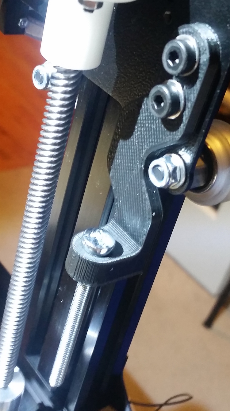
Step Twenty-Three: Lever Arm Assembly (Extruder Assembly)
You will need:
- Base Assembly
- Printed Lever Arm
- 2 Lever Arm Plates (R)
- 2 Extruder Idler Arm Inserts (Below F)
- 1 Small Bearing
- 1 Brass hob
- 1 T-Nut
- 1 M3-30 machine screw
- 1 M5-16 machine screw
- 4 M3-6 button head screws
- 1 M3-18 machine screw
- 3 M3 washers
- 1 M3 nut
- Thread locker
Use M3-6 button head screws to attach one Lever Arm Plate to the Printed Lever Arm – use the hole at the narrow end of the arm, and the middle of the holes at the other end.
Flip the arm over, and insert the two Extruder Idler Arm Inserts into the provided slots in the Lever Arm Plate before placing the second Lever Arm Plate over the other side of the Printed Lever Arm and attaching it in the same fashion.
Run the M5-16 machine screw down from the top of the lever arm (the smooth, convex curve), through the Extruder Idler Arm Inserts, and to the point where it emerges between the two square frames. Insert the T-nut and thread it onto the end of the screw with its ends trapped in the frames.
At the bottom of the “thick” end of the arm is a cutaway about half the thickness of the arm. Feed the M3-18 screw through from the thick side; as it enters the cutaway, thread it through an M3 washer, the small bearing, and another M3 washer. Secure it on the outside of the Lever Arm Plate with an M3 nut.
Install the arm with the M3-30 machine screw with a washer by the screw head. It installs through the remaining hole in the “thick” end of the arm and into the top-back hole we left open in the motor mount. Use thread lock on this screw, and tighten it snugly but leave the arm room to swing a bit.
Compress the included spring and fit it between the bottom of the T-nut and the printed platform below it. There’s a small pyramid in the printed shape to capture the bottom of the spring.
Finally, mount the brass hob on the shaft of the stepper motor. You’ll need to press the arm down to fit the hob into the space intended for it. As usual, the set screw tightens onto the flat of the shaft.
Step Twenty-Four: Hot End Assembly (Extruder Assembly)
You will need:
- Base Assembly
- E3D-v6 Hot End Kit
I’m going to hand this step off the manufacturer, who’ve provided excellent instructions here.
Step Twenty-Five: Hot End Installation (Extruder Assembly)
You will need:
- Base Assembly
- E3D-v6 Hot End (Assembled)
Trim the white PTFE tube on top of the assembled Hot End off close to the top of the hot end.
Raise the X-Axis assembly by turning the lead screws to give yourself plenty of room.
The silver cylinder of the hot end fits snugly into the cylindrical hole of the Aluminum Hot End Block. Work it up the hole until the end of the remaining stub of PTFE tubing is immediately below the brass hob. Two set screws go in through the front of the printed extruder body, through the aluminum block, and secure the hot end in place.
Now, look down on the extruder from above and look through the small hole in the top of the arm for the filament. You should be able to clearly see the tip of the white tube below. Adjust the position of the brass hob until the hole, the geared groove in the hob, and the white tube are in line, and re-tighten the hob’s set screw.
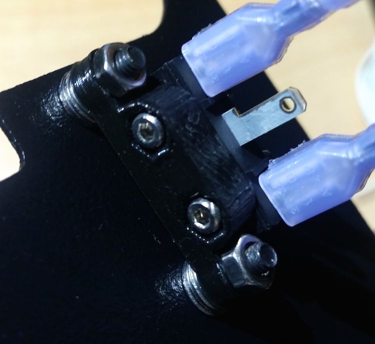
Step Twenty-Six: Y End Stop Installation
You will need:
- Base Assembly
- Y End Stop Printed Part
- 1 Microswitch
- 1 Switch Wiring Harness
- 1 M5-10 machine screw
- 2 M2-12 machine screws
- 2 M2 hex nuts
First, find this printed part:

The installed Y End Stop. (c) Maker’s Tool Works
As you can see, the microswitch mounts to the side of the part using two M2-12 machine screws and nuts. Orient the microswitch so that the tab is pointed away from the bulk of the part. Take one of the wiring harnesses (white and black wires, spade union connectors on one end and a two-pin jumper block on the other) and connect it to the end terminals on the switch.
Use the M5-10 machine screw to connect the printed part – it goes with the loose T-nut we installed way back when we started assembling the Y-Axis Assembly. Position the switch the way it’s shown in the photo – the thick part of the printed part should line up with the last screw head on the rear end of the Y-Axis Assembly.
You will need to bend the metal tab of the microswitch up a bit to make sure the wheel assembly of the Y-Axis Assembly makes contact with the switch.
Step Twenty-Seven: Z End Stop Installation
You will need:
- Base Assembly
- 2 Z End Stop Printed Parts
- Deck Side Back Plate (Not Shown)
- 1 Microswitch
- 1 Switch Wiring Harness
- 2 M5-10 machine screw
- 2 M5 washers
- 2 M5 hex nuts
- 2 M3-10 machine screws
- 1 M5-60 screw
- 8 M3 washers
- 2 M3 hex nuts
- 2 M2-12 machine screws
- 2 M2 hex nuts
NOTE: The official directions are significantly different due to a different design of the printed parts. If your kit’s parts don’t match these directions, take a look at the official ones.
First, locate the printed parts:
The first of the Printed Parts
And the smaller one:
The other printed part (already installed)
This part is very small, just a platform large enough to attach the microswitch and two screw ears at right angle to it.
The last part you need is this plate, which is not shown in the layout I’ve been using:
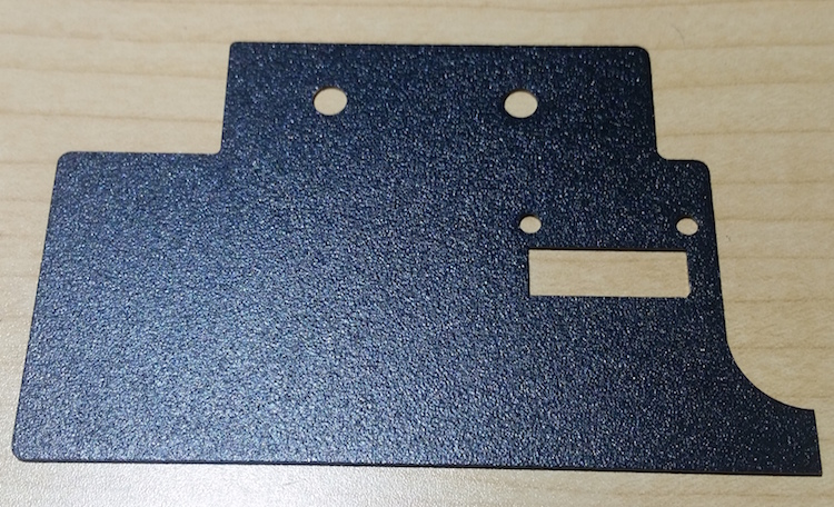
The Deck Side Back Plate (There are two of these)
This plate rests behind the vertical extrusion for the Z-Axis, with the two-hole flange resting on top of the extrusion that makes up the side between the straight and angled Z-Axis extrusions. The microswitch is installed on its printed support using two M2-12 machine screws and nuts with the ears of the support above the switch body. Then the support is suspended by two M3-10 machine screws below that rectangular hole in the plate. Stack four washers each between the plate and the support piece to get the switch low enough.
As with the Y-Axis, connect a wire lead to the outside terminals on the microswitch.
The upper printed piece is secured by two M5-10 machine screws and nuts to the Z-Axis Carriage Plate on the side you install the microswitch (I used the left, but it doesn’t actually matter.) The dogend in the piece fits around the screw head for the wheel on the carriage plate. Thread the M5-60 bolt through the ear suspended by the piece such that it makes contact with the microswitch, and you’re done.
Step Twenty-Eight: X End Stop Installation
You will need:
- Base Assembly
- X End Stop Printed Part
- 1 Microswitch
- 1 Switch Wiring Harness
- 1 M5-10 machine screw
- 1 T-nut
- 2 M2-12 machine screws
- 2 M2 hex nuts
The X End Stop printed part has the switch mounted vertically on it’s little tab, on the same side as the ear with the screw hole in it, using the M2-12 machine screws and M2 hex nuts. The hinge of the switch should be towards the ear; it’ll catch if it’s reversed.
Slide the T-nut into the bottom channel of the X-Axis Assembly, over on the far left end (opposite the motor.) Mount the printed part there with the screw ear flush or nearly flush with the end of the extrusion.
You’ll need to bend the terminals of the switch out away from the printed part to connect the wiring harness.
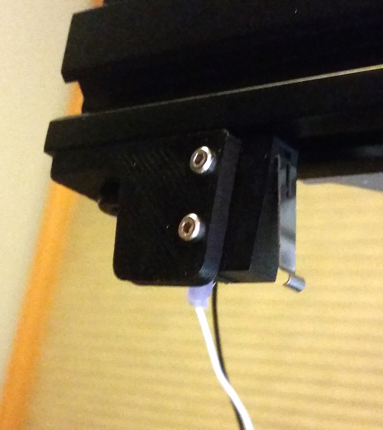
The installed X-Axis End Stop
And with that, I need to bring Day 3 to a close. We’re getting close to the end; I firmly believe tomorrow will end with at least electrically-controlled movement of printer parts, if not, just maybe, the start of a calibration print.
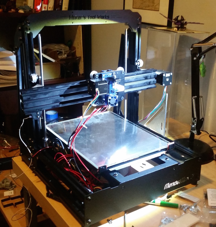
Day 3.